
Key Sourcing Takeaways
- Never adjust key click feel by swapping compound Shore A alone: peak actuation force (Fp 50–350 gf) and collapse snap ratio ((Fp − Fc) / Fp, ideally 40%–60%) are controlled primarily by the slanted cone webbing thickness (0.25–0.65 mm) and cone angle (40°–60°).
- Always cut underside air-vent channels connecting isolated switch pockets unless sealed front-face IP ingress rules forbid venting; trapped compressed air turns crisp key domes slow and mushy upon release.
- Match contact architecture to real life-cycle duty: mold vulcanized carbon conductive pills (<100 Ω typically) for quiet, cost-effective industrial membrane PCBs, or pair solid elastomeric actuator pins over stainless snap domes for sharp short-stroke click.
Silicone Keypad Force-Travel Curve, Snap Ratio & Carbon Pill Spec
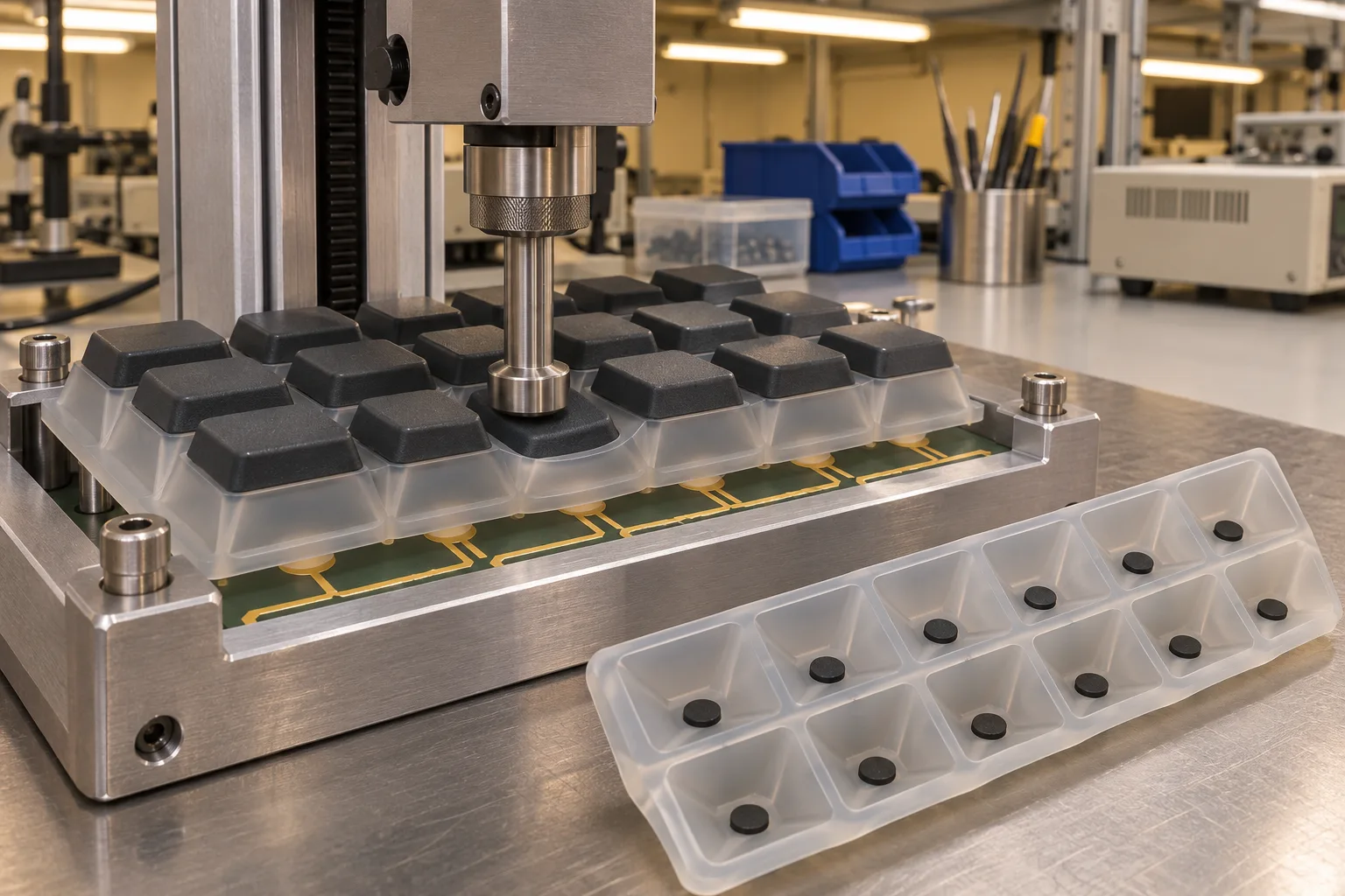
On any keypad interface—whether a rugged outdoor terminal, diagnostic analyzer, remote control, or instrument panel—buyers immediately notice two things: does a key register cleanly on the first press, and does it return smoothly without binding in the front bezel? Getting both right has far more to do with three-dimensional skirt cone buckling geometry (±0.05 mm webbing precision) than printing a higher Shore A number on the blueprint.
Inside Dongguan Youbang's 8,000 m² plant (pairing our 5-axis CNC/EDM toolroom, 15 vacuum HCR presses, in-house screen printing/laser-etching backlight booth, and P+R plastic-plus-rubber assembly stations), engineers calibrate force-displacement curves systematically before releasing production tooling.
1. Actuation Geometry Inputs vs. Measurable Feel Outputs
Tune key actuation force (50–350 gf) and travel (0.5–3.0 mm) by editing cone angle, webbing thickness, and base durometer together—never rely purely on base rubber hardness. Always measure actual T1 keypads mounted on the production PCB inside its bolted plastic bezel.
| Engineering Lever Inside Mold CAD | Direct Impact on Force Curve (Fp & Fc) |
Typical Production Target Window | Shop-Floor Tuning & Risk Guardrail |
|---|---|---|---|
Slanted Webbing Wall Thickness (t) |
Raises or drops peak actuation force Fp roughly exponentially (∝ t²–t³) |
0.25–0.65 mm molded skirt thickness |
Controlled via 5-axis CNC/EDM electrodes (±0.05 mm tight critical webs) |
Cone Skirt Angle (θ) |
Governs buckle sharpness and tactile snap ratio (Fp − Fc) / Fp |
40°–60° cone incline angle |
Too vertical (>65°) locks rigid; too flat (<35°) washes out snap drop |
| Base Elastomer Hardness | Shifts baseline stiffness + rebound recovery speed across temperature | 45–65 Shore A (typically 50–55A sweet spot) |
Use stable 200 °C × 4–6 hours post-cured rubber to freeze modulus |
| Air-Vent Relief Channels | Eliminates trapped pneumatic air cushion slowing rebound | Recessed 0.15–0.30 mm base channel vents |
Mandatory where keypad skirts seal perimeter bezel holes hermetically |
| Bezel Side Wall Clearance | Prevents off-center angled presses from scraping or sticking inside bezel | Minimum 0.20–0.35 mm radial gap per side |
Test off-center 30° thumb edge press on assembled front frame at T1 |
2. Sizing Crisp Snap Ratio Without Cracking the Skirt Root
When a plunger pushes a molded keypad top downward, the force-displacement curve climbs cleanly to Peak Force (Fp, commonly 50–350 gf), buckles sharply at the angled skirt cone, and drops into Contact Force (Fc) as the underside carbon pill or plunger touches the PCB:
- Snap Ratio Equation:
(Fp − Fc) / Fp × 100%. Targeting40%–60%gives clear finger confirmation without needing to stare at the screen. - Root Blend Radii Stop Fatigue Tearing: Keep small inside/outside transition fillets at the top hinge and flat PCB foot (
≥0.2–0.3 mm) rather than dead-sharp 90° corners, preventing cyclical white stress cracks after heavy switch testing.
3. Carbon Pills, Metal Domes & P+R Keycaps — All Verified Together
Depending on travel and cosmetic finish requirements:
- Vulcanized Carbon Conductive Pills: Compressed directly into key centers (
<100 Ωcontact resistance on clean ENIG gold-plated PCB pads) with silent zero-click return—ideal where sealed dustproof quiet operation matters. - Rubber Plungers + Snap Metal Domes: Molds firm center nibs (
0.15–0.30 mmpreload gap) pushing stainless PCB domes when crisp audible clicks and short travel dominate. - Custom P+R (
Plastic Cap + Rubber Base) & Legends: Buyer-supplied molded PC/ABS keycaps mount onto our silicone base pads, finished in-house with multi-color screen printing, laser-etched backlit characters, and anti-dust soft-touch topcoat from100 pcspilot lots upward.
Ready to balance click feel on your enclosure stack? Upload your top bezel, keypad outline, and PCB pad height on our custom keypads & buttons page or review a live glove-operated industrial P+R controller case study for a first engineering reply within 24 hours.