
Youbang · B2B Custom Silicone Manufacturing · Dongguan

Custom Molded Silicone
Gaskets & Enclosure Seals

Engineer custom flange gaskets, perimeter housing groove seals, diaphragm boots and metal/plastic-carrier overmolded seals across 0–80 Shore A silicone, EPDM, NBR and FKM—combining LSR & HCR molding, typical ±0.05 mm critical fit tolerances, and 2D optical dimensional verification.

Two examples of how a seal meets the joint

A round ring can seal a face, and an irregular perimeter can sit in a groove. Outline, section and retention are separate choices; these examples do not divide every seal into two exclusive categories.

Youbang Silicone

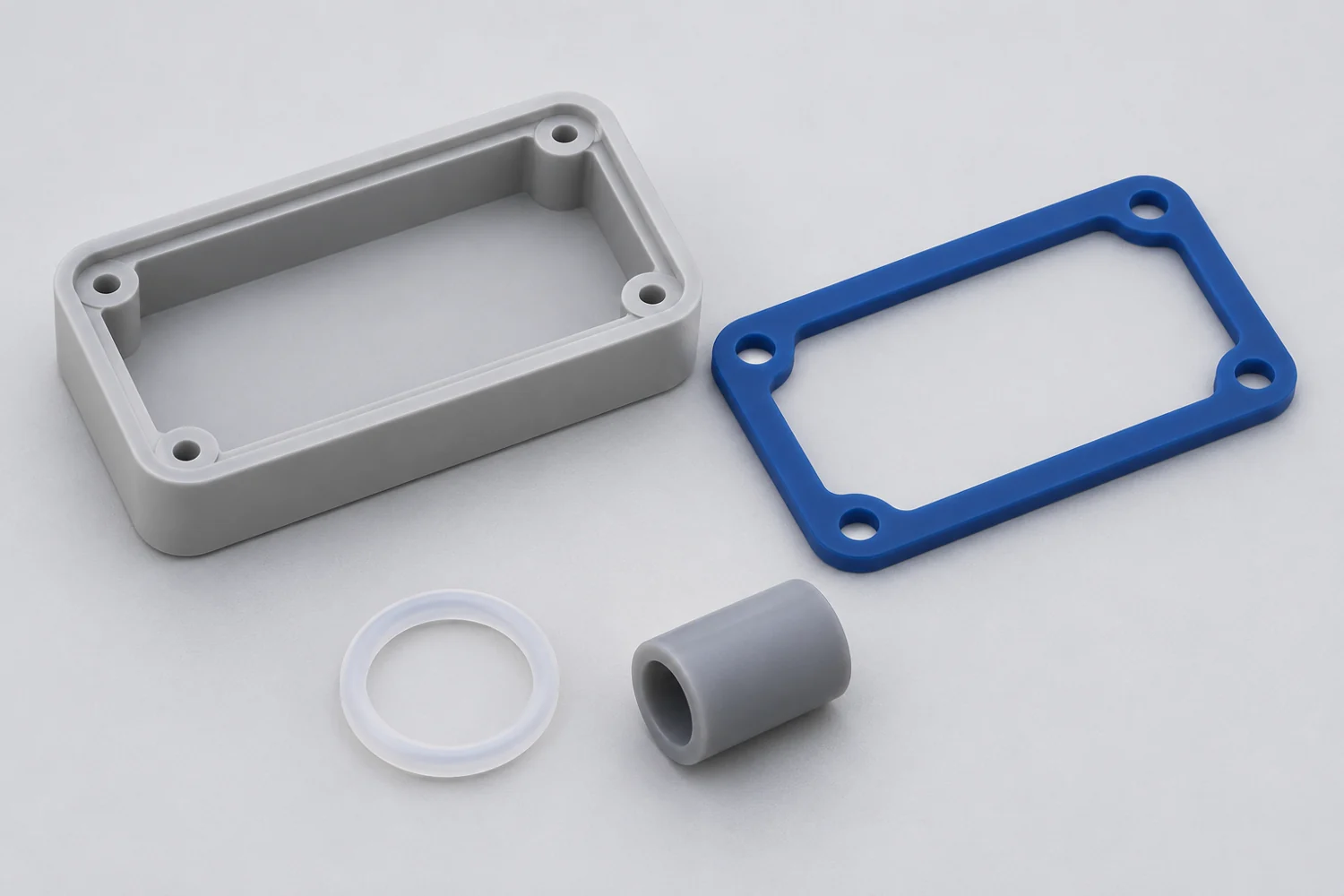
A gasket clamped between faces

A gasket follows a sealing path between mating faces. The path may surround an opening, pass around fixing features or use locating holes to stay aligned as the assembly closes.

A broad contact band and a narrow profile occupy the available flange differently. Corners, fastener positions and the closing motion affect where the part can move or become unevenly compressed.

Mating relationship · Show both faces, the sealing path, locating features and the assembly stops—not only the loose gasket outline.
Rings and mating grooves

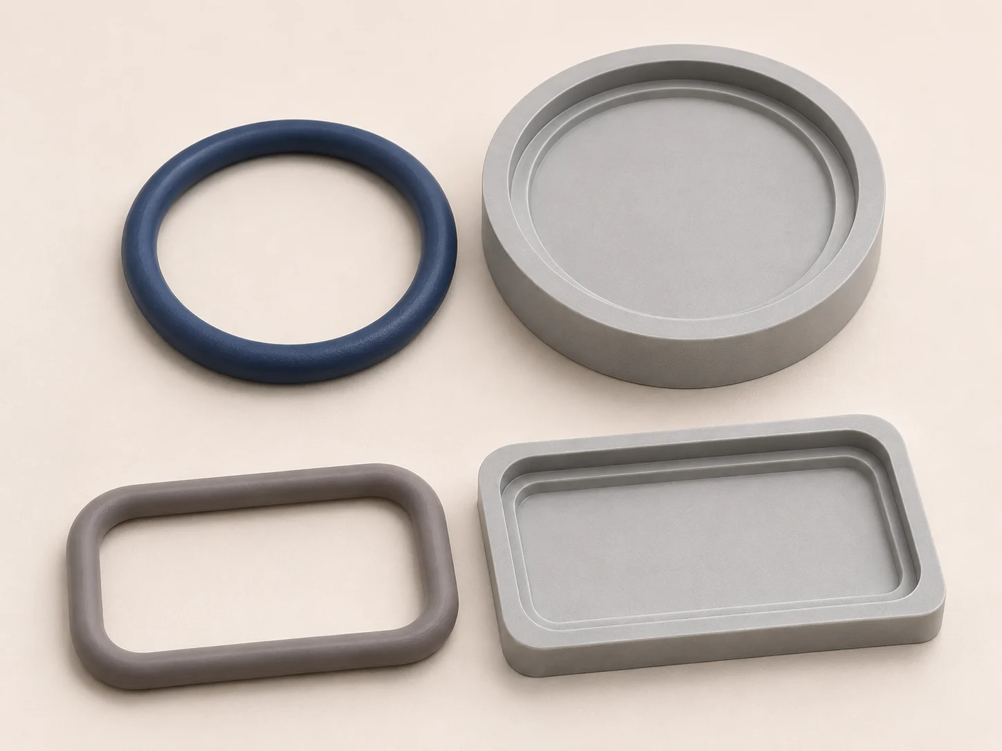
A seal located by a groove

A groove locates the section while the opposing surface closes onto it. Circular and non-circular paths can both use this relationship, depending on the joint.

The groove must leave space for the material to deform without losing the intended contact. Insertion edges and the path through which the seal is fitted also matter.

Mating relationship · Define groove width and depth, section shape, the closed gap and how the seal is retained during assembly.

Connect the section to the closing movement

The schematic shows a section seated in a groove and a separate mating face. Use the actual assembly limits to define the compressed condition; it is not a universal compression ratio.

Engineering Interface Cross-SectionUpper Mating Flange · Elastomer Seal Section (20–35% Squeeze) · Gland Groove & Lateral Expansion Space. Engineering interface schematic; final tolerances confirmed per project CAD.Air GapAir GapUpper Mating FlangeElastomer Seal Section (20–35% Squeeze)Gland Groove & Lateral Expansion Space
Engineering cross-section schematic (not to scale; wall thickness and tolerances confirmed per project 3D CAD).

Section and available space

Compare the loose section with the groove and the closed gap. Include dimensional limits so the review covers more than a nominal drawing position.

Closing, fastening and stops

The way the faces meet affects contact around the path. Show fastening locations, assembly direction and stops that set the final gap.

Location and installation access

Check whether the part shifts while closing and whether it passes sharp edges, threads or tight corners during installation. Plan removal if the joint is serviced.

Describe what the assembled joint will experience

Operating contact

Identify the contacting medium, temperature and exposure time, including intermittent changes or pressure differences where relevant. A material family name alone does not establish compatibility.

Movement and reopening

These examples focus on static joints. If faces slide, rotate or repeatedly open, state the motion and frequency so the contact and material questions are assessed separately.

Cleaning and maintenance

Cleaning agents and temperatures can differ from normal service. Record removal, refitting and residue-cleaning needs with the intended maintenance routine.

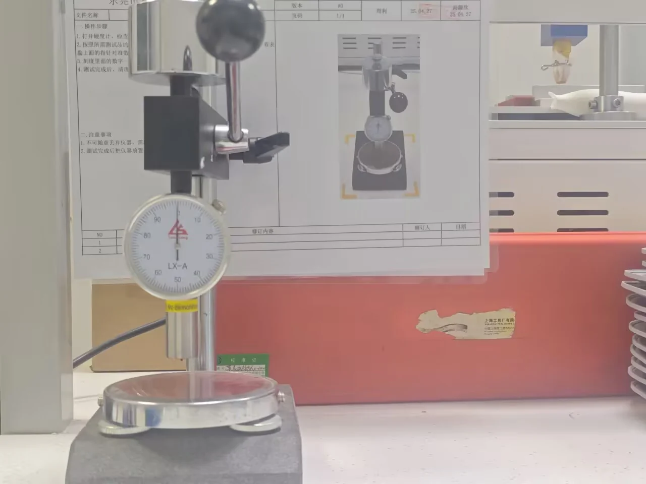
Hardness measurement equipment

Check the part, then the assembled seal

Hardness and dimensional checks describe the molded part. Sealing behavior belongs to the actual mating assembly, using the agreed medium, method and acceptance criteria.

  1. Part condition

    Record the sample revision, critical dimensions, sealing-edge appearance and selected material documents. Inspect the features that locate the part.

  2. Installed condition

    Fit the part into the intended joint and observe location, closure and removal. Check the gap or stops against the drawing before interpreting a leak result.

  3. Assembly acceptance

    Agree the complete assembly, contact medium, loading and test method. Record results against that configuration rather than treating a loose gasket as an enclosure rating.

Choose a 3D sample only where geometry or fitting needs clarification. Use molded silicone to observe deformation and contact; match material records to the selected grade and batch.

Sourcing & Tooling FAQ

Key Answers Before Tooling

Covering CAD readiness, custom MOQ evaluation, free 3D fit checks vs. T1 silicone samples, NDA protection and mold ownership.

Have a part-specific question?

Send your drawing or sample photo directly to Zhou Li’s engineering desk for a 24h DFM reply.

How do you select between LSR, solid HCR silicone, EPDM, NBR and FKM for custom seals?

Silicone excels across wide outdoor/thermal swings, UV/ozone exposure and RoHS/REACH or FDA/LFGB compliance—molded via 85T/120T LSR injection for thin walls (down to 0.25–0.30 mm) and flash-sensitive ribs, or 200–250T HCR compression. Where joints contact hydrocarbon oils, fuels or aggressive solvents, we also compression-mold EPDM, NBR (nitrile) and FKM (fluoroelastomer) seals.

Can we reverse-engineer a replacement seal from a worn field sample, or overmold onto rigid carriers?

A field-aged gasket often shows compression set or fluid swell, so share both the physical part and the mating groove/flange CAD so we restore proper uncompressed interference. Where seals bond directly to rigid frames, customer-supplied stainless steel, aluminum, copper, PC, PP or PA carriers are overmolded with silane primer.

How do you verify tight tolerances and enclosure ingress sealing before mass production?

On 7–15 day T1 molded samples, we inspect critical cross-sections (typical ±0.05 mm on precision features, evaluated per CAD) and Shore A hardness using our 2D optical vision system and calibrated durometers. Final IP water/dust ingress performance belongs to the assembled housing stack and is validated directly inside your mating enclosure.

B2B Factory Direct · 24h Engineering & Tooling Review

Submit Your Gasket or Groove-Seal CAD for DFM Review

Share your seal + mating groove 2D/3D CAD, Shore A durometer, operating media/temperature and target volume—receive engineering feedback within 24 hours.

✓ NDA available before CAD exchange✓ Eligible for 1–3 free 3D fit prototypes✓ Paid molds 100% owned by customer

Helpful RFQ Inputs

  • Mating or groove drawings and assembly stops
  • Service medium, temperature and maintenance
  • Acceptance target, reference and quantities